


| | | This page pictorially shows how to build a Low Flying Aircraft Monitoring System. The camcorder is used somewhat like a sextant which is used to measure the angular distance between the ocean's horizon to a celestial object. Since the monitoring system is being used over land we have to create our own horizon. This artificial horizon is identified somewhat like using a rifle when the front and rear sights are level with each other. The camcorder is at the position of where your eye would be when sighting the rifle. When the two sights are level with each other then the sights will point to the artificial horizon. You would have to add the height of the sight's height above the ground when doing the final calculation for the airplanes altitude. There is another web page (http://lowflying.com/certification_plan.htm) that has the Certification procedure for the Low Flying Aircraft Monitoring System. This procedure also describes how to calibrate and use the monitoring system once it is built. The Certification procedure would be used to verify that a newly built Low Flying Aircraft Monitoring System works correctly. |
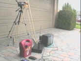 | This is what the equipment at one of the two monitoring sites looks like. The other site would be about a mile away facing this one. | 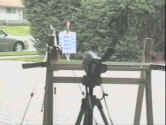 | The camcorder is looking over the rear sight towards the front sight. The two sights are at the same level and form the artificial horizon. | 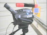 | The camcorder is looking over a bubble level. The white bubble level forms the rear sight of the artificial horizon. The yellow & blue box is the electronic level measurer. | 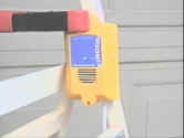 | This is an electronic water level measurer. It is used to ensure that the front sight is at the same level as the rear sight. The rear sight is the white bubble level just to the left of it. | 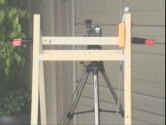 | This is a front view of the camcorder looking over the rear sight of the artificial horizon. The yellow box to the right is the electronic leveler. it is next to a white straightedge bubble level. |
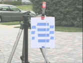 | This is the front sight. The target is mounted on a tripod which has the far end of the electronic leveler clear tube attached to it. The front sight is moved up or down to make it level with the rear sight. |
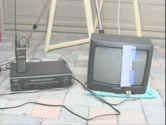 | The VCR records both video and audio. The video from the camcorder of the airplane is recorded by the VCR. The VCR also records audio from the air traffic radio. The white patch on the TV screen is a paper template with degrees on it to measure the elevation angle |
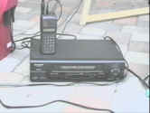 | The multi-band radio's phone jack plugs directly into the VCR. It records the aircraft radio traffic on the same videotape that the airplane is being recorded on | 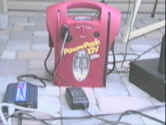 | This is a power pack (12 volt gel battery) which supplies power to a DC to AC inverter. This is only necessary if no other AC power is available. | 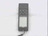 | This is a hand held GPS receiver. I've used the Garmin 12 XL. |
TOP | These next three items are not necessary but are nice to have. The 2-meter band radio does require you to pass a FCC license test before using it. |
 | This is a hand held transit. A fancy name for a bubble level with a cross hair sighting. It is helpful when setting up the artificial horizon. |
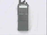 | When setting up the equipment it is nice to have some communication between the two sites. Cell phones work very well. I use this 2-meter band hand held HAM radio. |
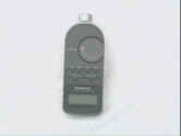 | This is a sound level meter from Radio Shack. It is not necessary for the monitoring system. However, it does give you a measurement of what you are trying to reduce. |
TOP | Once you have your camcorder and if this particular camcorder has not been calibrated, it needs to be calibrated. Since I already have things set up for doing the calibrations, I could easily calibrate your camera for you. The camera company should be able to supply the lens data for your camera. I used the Panasonic PV-D209 and chose to do my own calibration. Here are three different ways that I calibrated my camcorder. These next three items are for calibration, verification and validation. |
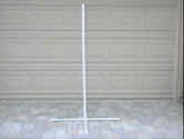
| Two of these PVC pipe stands are used to make a scale model test of the camcorder's angle measuring ability. One pipe stand is placed at two of the corners of a triangle. The camcorder is placed at the third corner. The camcorder's wide angle lens ability to see the 3/4" PVC pipe is limited to about 100 feet. So you should make your triangle no more than that distance. With the camcorder in its normal upright position you would be measuring the camcorder's azimuth angle. But, by turning the camcorder 90 degrees, you would now measure the camcorder's elevation angle instead of its azimuth angle measurement. |
 | Two of these and a camcorder were used to create a large triangle in a parking lot. By knowing the dimension of the triangle you know the angle of the triangle. |
| A protractor is used to verify the accuracy of the camcorder as an angle measurement device. But why a giant protractor? When measuring something close-up with optics, the accurate placement of the viewing lens becomes important. A 1/4 inch placement error of the viewing lens of a protractor with a 6-foot radius would result in about a .4% error. The same 1/4 inch error in a protractor with a 2.5 inch radius would be 10%. This system error is over 20 times larger. Bigger is better because a fixed 1/4 inch error has less effect on the total system accuracy. |
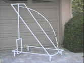 | This is a giant 90 degree protractor made out of PVC pipe. The radius is 57.30". 1" distance on the circumference of the curved part is equal to 1 degree. |
TOP | The United States Naval Observatory publishes the angular elevation angle to celestial objects. If you know what time it is, the Observatory can tell you what the elevation angle to the sun is in reference to your location. The Observatory's data was used to calibrate and verify the accuracy of the camcorder as an angle measuring device. This setup has a couple of features which make it ideal for verification of this system. Firstly, the United States Naval Observatory is the industry standard for this type of data. Secondly, even if the location of the observation lens (see Giant Protractor above) was off by 6 miles the max elevation angle error would be less than 1/10 of a degrees. |
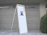 | This was built to videotape the sun with the camcorder The black square in the center is a #14 welders shade. There is an opening just below the shade for viewing the artificial horizon. |
|